13. Working principle and specification
This chapter describes the working space, working principle, size and key technical specifications of WLKATA Mirobot.
Working space
The workspace of WLKATA Mirobot.

Coordinate system
WLKATA Mirbot has a six-joint coordinate system and a Cartesian space coordinate system.

1 Joint coordinate system: the coordinate system determined by reference to each moving joint.
•This manipulator has six joints: j1 j2 J3 J4 J5 J6, all of which are rotary joints. The positive rotation direction of each joint follows the right-hand rule and the thumb points to the opposite direction of the output shaft of each shaft motor.
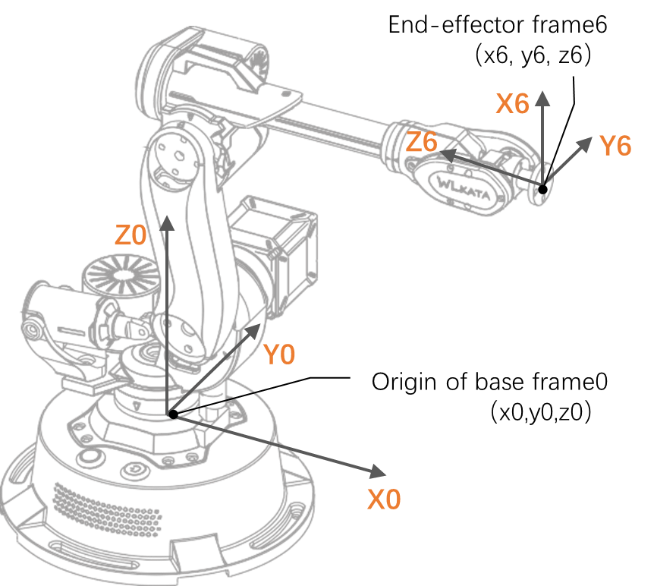
2 Cartesian coordinate system: The coordinate system is determined by reference to the base of the manipulator.
•The origin of the coordinate system is the center of the base platform.
•The x-axis direction is perpendicular to the fixed base forward.
•The y-axis direction is perpendicular to the fixed base to the left.
Sports function
The motion modes of Mirobot manipulator include Joint motion mode and Coordinate mode.
1 Joint motion mode:
the Joint motion mode means that each joint of the manipulator is controlled separately. You can click the joint motion button to move a single joint.
•Click "J1 +" and "J1 -" to control the positive and negative rotation of the base motor.
•Click "J2 +" and "J2 -" to control the positive and negative rotation of boom motor.
•Click "J3 +" and "J3 -" to control the positive and negative movement of jib motor.
•Click "J4 +" and "J4 -" to control the positive and negative rotation of the fourth axis at the end.
•Click "J5 +" and "J5 -" to control the positive and negative rotation of the fifth axis at the end.
•Click "J6 +" and "J6 -" to control the positive and negative rotation of the sixth axis at the end.
2 Cartesian motion mode:
The Cartesian motion mode of the manipulator controls the position and attitude of the en-effector. You can click the coordinate and RPY angle motion buttons to change the position and attitude of the end actuator.
•Click "x +" and "X -" to control the manipulator to move along the positive and negative direction of the X-axis.
•Click "Y +" and "Y -" to control the manipulator to move along the positive and negative direction of the Y-axis.
•Click "Z +" and "Z -" to control the manipulator to move along the positive and negative direction of the Z-axis.
•Click "PX +" and "PX -" and the end posture of the manipulator rotates along the X-axis.
•Click "py +" and "py -" to rotate the end posture of the manipulator along the Y-axis.
•Click "PZ +" and "PZ -" and the end posture of the manipulator rotates along the Z-axis.
The Cartesian motion mode supports point-to-point motion mode and linear interpolation motion mode. Please refer to the WLKATA Mirobot communication instructions for specific modes information.
Technical specifications
| name | parameter |
|---|---|
| Axle number | 6+1 |
| Payload | 150g |
| Repeated positioning accuracy | 0.2mm |
| Communication Interface | USB/WiFi */Bluetooth |
| Power supply voltage | 100V-240V, 50/60 Hz |
| Power input | 12V/5ADC |
| Power | 60W Max |
| Working environment | -10°C~60°C |
| Shaft | working range | maximum speed |
|---|---|---|
| Axis 1 | -100° to +100° | 31°/s |
| Axis 2 | -60° to +90° | 65°/s |
| Axis 3 | -180° to +50° | 28°/s |
| Axis 4 | -180° to +180° | 110°/s |
| Axis 5 | -180° to +40° | 33°/s |
| Axis 6 | -180° to +180° | 66°/s |
| name | parameter |
|---|---|
| Net weight (manipulator and controller) | 1.5kg |
| Round base size | <diameter160mm |
| Material of manipulator | Aluminum alloy, ABS engineering plastics |
| Controller | Arduino2560 |
| Robot installation | Desktop |
| Package specification (L×w×h) | 220mm×160mm×270mm |
| The dimension of standard outer box (L × w × h) | 300mmx200mmx400mm |
Technical parameters
The size parameters of WLKATA Mirobot are shown in Figure below.

